Measure Twice, Install Once
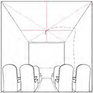
Square up the room and locate where the first panel will be installed. A slight error on the first panel can become a major alignment issue by the end of the room.


 Install Guide
HT Design installation reference
A customer-ready web version of the surface mount star ceiling instructions, with safety notes, packing details, installation sequence, power options, iGlo lighting notes, and product specifications.
Surface mount star panels are plug-and-play acoustic panels with the fiberoptic star ceiling experience built in. They install onto finished surfaces and require a low-voltage 12v DC connection.
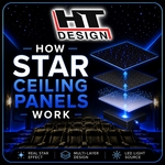
Each panel has a low-voltage star engine built in. A driver powers the first panel through a leader cable, and jumper cables daisy chain power from one panel to the next. For installations with more than 133 panels, add additional drivers and leader cables to the same switched circuit.
Panels are made with Class A fiberglass and covered in a Class A fabric or vinyl finish. Wiring harnesses are made from CL2 and CL3 or higher rated materials. For plenum installations, the installer must supply CL2P, CL3P, or CMP-rated wiring and confirm local code requirements.
 Star Field
 Skylight
 Coffered
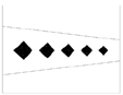 Diamonds
Plan the installation around the design, site conditions, code requirements, and the first panel's alignment. The first panel determines the line for the rest of the room.
Make sure all code requirements are fulfilled. If the project requires an electrical permit, the installation will be subject to local electrical code requirements. When in doubt, consult the local permitting authority.
Electrical codes generally follow the National Electrical Code (NEC), published by the National Fire Protection Association. The NEC is intended to reduce hazards from electrical shock, fire, and toxic fumes caused by exposure to fire.
Warning: Disconnect power before beginning any electrical work, and do not exceed the capacity of the circuit.
Each master pack ships with panels, mounting hardware, jumper cables, gloves, and instructions.
| Panel Size | Panels per Master Pack | Mounting Points per Panel | Anchor / Screw Sets per Master | Jumper Cables per Master | Powder Free Latex Gloves | Instructions |
|---|---|---|---|---|---|---|
| 24" x 24" | 6 | 4 | 24 | 6 | 2 | 1 |
| 30" x 30" | 6 | 4 | 24 | 6 | 2 | 1 |
| 48" x 48" | 2 | 6 | 12 | 2 | 2 | 1 |
| 48" x 96" | 1 | 10 | 10 | 1 | 2 | 1 |
First-time installers should purchase an installation kit.
Use masking tape, pencil marks, chalk lines, and careful measurement to keep the installation square. Every panel aligns from the first panel, so take time to establish a true starting position.
Square up the room and locate where the first panel will be installed. A slight error on the first panel can become a major alignment issue by the end of the room.
Use a remote driver and pre-installed leader cable when practical. The selected outlet should be controlled from a remote switch or control system, and the leader cable should not be longer than 30 feet unless reviewed for the project.
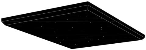
Place the first panel on the ceiling in its proper orientation. Two people should perform this step, and larger 48" x 96" panels should use at least three people. Push an awl through the marked points to indent the ceiling, then remove the panel.
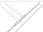
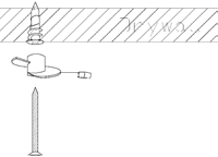
EZ anchors are for drywall only. Use them only in 5/8" drywall with wood framing. All other conditions require the installer to source an appropriate alternate attachment method.
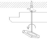
Connect the leader cable, turn on the driver, and confirm the stars illuminate. Insert hex drivers through the marked face holes, apply gentle upward pressure, and rotate counter-clockwise until the panel pulls flush. Do not overtighten.
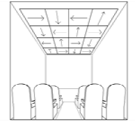
Each panel is marked with an orientation arrow. Rotate panels one quarter turn for a more random starry night effect. The 48" x 96" panels can only be rotated 180 degrees.
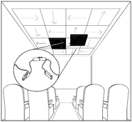
Leave plugs hanging off the side so the next panel can connect. Connect a jumper cable from the first panel to the next panel's star engine. Jumper cables may be sandwiched between the ceiling and panel or routed along the 2" light cove.
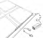
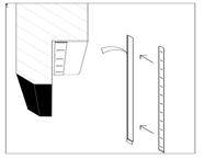
Mount the iGlo LED strip on the panel light cove where light should originate. Spanners bridge between panels and should be installed after panels are mounted. If light leaks at seams, use a half spanner over the seam to block the leak.
Select the power approach based on the site condition, design intent, and code requirements. Always check and observe local building codes.
Recommended method. Locate the driver in an accessible equipment area within 30 feet of the first leader cable and daisy chain panels with supplied jumper cables.
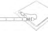
Optional anchors allow panels to hang from the ceiling by chain. This typically requires at least 4 inches of total height and may not suit low ceilings.
Only a licensed electrician should embed the driver into a panel. The driver is a line-voltage device and generally requires access through a panel cutout.
Panels use premium 6 lb. density acoustic fiberglass, square edges for easier installation, and standard black fabric. Other colors may be available upon request.
| Shared Specification | Value |
|---|---|
| Thickness | 1" or 2" |
| Color | Black Onyx |
| Star Color Temperature | 6500 K |
| Power Requirement | 12v DC |
| Power Consumption | 0.36w |
| Fiberglass | 6 lb. density |
| Noise Reduction Coefficient | >1.0 N.R.C. |
| No Cut Zone | Each panel has an 8" no cut zone marked on the back. |
HT Design branded web version. Technical content retained from the supplied installation sheet; verify final project requirements against local code and job-site conditions.